(Written by Vladimir Horvat - updated on October 20, 2021)
The purpose of this program is to control positioning of the device under test (DUT), slit apertures, and beam energy degraders.
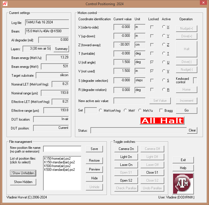
The main application window is divided into several areas. Their purpose, usage, and functionality is described in the following sections.
Current settings group contains a set of read-only edit boxes that display the relevant information and static text that briefly describes their content. A more detailed information is provided below:
Motion control group contains a set of read-only edit boxes that show the current position of the device under test (DUT) in terms of its coordinates X, Y, Z, and T. Coordinate T is the tilt angle of the mounting frame with respect to the beam. When the DUT is inside the vacuum chamber, X and Y are the horizontal and vertical coordinates of the DUT in the mounting frame plane, while the Z axis is horizontal and perpendicular to the mounting frame. When the DUT is in air, Z axis is along the ion beam axis, while X and Y are the horizontal and vertical coordinates, respectively, both being perpendicular to Z.
In the "Vacuum chamber" setup coordinates U and V specify the aperture of the horizontal and vertical slits, respectively. In the "In-air" setup coordinate U specifies the DUT roll angle, while coordinate V is unused.
Coordinates S and R specify the aluminum degrader thickness. S specifies the selected degrader and has to have an integer value. R is the tilt angle of the degrader. When S is zero, the beam is not degraded and R coordinate is irrelevant.. Otherwise, the effective degrader thickness in mil (1/1000 in.) equals 2S-1/cos(T). Values of R over 60° are not recommended because they result in large uncertainty of the degrader effective thickness. They can be avoided by increasing S (i.e., by using a thicker degrader).
The coordinate along an axis can be changed (to move the DUT) after selecting that axis using the appropriate radio button. The control buttons are labeled in plain english and should be self-explanatory. They allow for the continuous movement (driving of jogging) in the positive or negative direction, stopping (halting) the movement, and for making small increments or decrements (nudging) in either direction. Clicking the Home button sends the system to its home position, which resets the position calibration. This needs to be done for each axis whenever the setup changes from "In-air" to "Vacuum chamber" or vice versa and after rebooting the computer. It may be necessary to do this for an individual axis if at any time the motion is impeded by a physical obstacle or if the vertical position changes due to excessive weight of the DUT.
To set a coordinate to a certain value, either the new value or the (signed) increment from the current value can be enterd in the edit box below. The motion is activated by clicking the adjacnt Set Value or Increment button, as appropriate.
The controls in the row below are used to adjust the beam energy or its Linear Energy Transfer (LET) to the desired value just below the beam entrance surface of the substrate. The appropriate radio button (indicating the unit of measure of the quantity that is to be specified in the edit box on the left) must be selected first in order to enable entering and editing the input data. If Bragg check box is selected, the beam parameters will be set to their Bragg-peak values (corresponding to maximum LET). To complete the operation, click the Go button on the right.
The check box labeled "Enable direct control of the (positioning) hardware" is for troubleshooting and should be done by the authorized cyclotron presonnel only. The users of the facility are strongly discouraged from using this feature as its improper use may cause damage to the equipment and even result in personal injury.
This program allows simultaneous movement of the target along several axes at a time. This feature should be used with caution, keeping in mind that clicking the Halt button stops only the motion along the currently selected axis. Clicking the All Halt button, on the other hand, stops all motion. In most cases, the same function can be activated by pressing the space bar on the keyboard. However, this feature works only while the cursor is in the edit box labeled Keyboard control. The cursor will be positioned there after any kind of motion is activated, but the users will not be prevented from arbitrarily moving the cursor somewhere else after the motion starts.
The up-to-date status of the positioning system is displayed in the status box. Click Clear to erase the currently displayed message.
The purpose of this group is to allow the users to save the current coordinates as a set, as well as to retreive and set (i.e., restore) them at a later time. To save the current set of coordinates, choose an appropriate name for it and enter it in the edit box at the top. Then click Save. To restore a saved set of coordinates, click its file name in the list below. Then click Restore to complete the operation. Before restoring the saved position, the coordinates to be set can be previewed by clicking Preview.
A position file name can be removed from the default list of unhidden files by clicking Hide. However, that file name cannot be used again for another set of coordinates. A list of hidden position files can be shown by clicking Show hidden. Note that Restore and Preview are enabled for the hidden positioning files. A file selected by its name from this list can be unhidden by clicking Unhide. A list of unhidden position files can be shown or refreshed by clicking Show unhidden.
This group contains the buttons that can be used to turn on or turn off the camera, the laser pointer, and the light in the vacuum chamber. It also contains the buttons that can be used to open and close the shutters installed in the beamline. The use of these four buttons in strongly discouraged, except for troubleshooting.
For the system used with the K500 cyclotron, the last row of buttons can be used to check for camera parallax. Clicking Check Parallax causes the target to move closer to the camera. The area seen by the camera at that position corresponds to the area exposed by the beam in the original position. Clicking the Undo Parallax button restores the original position.
For the system used with the K150 cyclotron, the last row of buttons can be used to turn the installed cross-hair generating lasers on and off. For the system used with the K500 cyclotron, these lasers are to be manually plugged in and out at the site.