(Written by Vladimir Horvat - updated on October 22, 2021)
The control software (program Seuss) at the Cyclotron Institute Radiation Effects Facility, Texas A&M University, is written as a Microsoft WindowsTM application and has the graphical users interface (GUI) typical of the Windows-based applications. The goal of program Seuss is to be as easy to use as possible. It has no menus to go through in order to activate the desired feature. Most of the features can be activated using the mouse, so that the need to use the keyboard is minimized. Buttons and edit boxes are labeled in plain English and those that are not available in the given context are disabled or hidden. Guidance via pop-up message boxes is provided for the procedures that require more than a single step.
The latest (2024) version of the control software for the Cyclotron Institute TAMU Radiation Facility (SEUSS) is included in the ZIP archive that can be downloaded from
https://mare.cyclotron.tamu.edu/vladimir/SEUSS-32.zip (32-bit version) or
https://mare.cyclotron.tamu.edu/vladimir/SEUSS-64.zip (64-bit version).
Files contained in the downloaded archive should be extracted into an EMPTY folder of your choice using a program such as 7-Zip program (which may be included in your Windows installation) or WinZip, which can be downloaded from
To start the program, run SeussW.exe. You may want to make a shortcut to this file and put it on your Desktop or in another folder of your choice. The program should run as intended on any Windows operating system that features Notepad text editor and a web browser. The screen resolution should be at least 1024 pixels × 768 pixels. Response from the Facility hardware will be emulated.
The 32-bit and 64-bit versions of SEUSS should run on Windows 7 or later operating system, but only the 32-bit version will run on Windows XP.
Linked hypertext help pages can be accessed by pointing your browser to file named SeussW.htm located in the installation folder or on-line starting at
https://mare.cyclotron.tamu.edu/vladimir/SeussW.htm.
A tutorial for new users can be downloaded from
https://mare.cyclotron.tamu.edu/vladimir/SEUSS-Tutorial.pdf (368 kb).
SEUSS software can be completely removed from the host computer by deleting the folder in which it is installed.
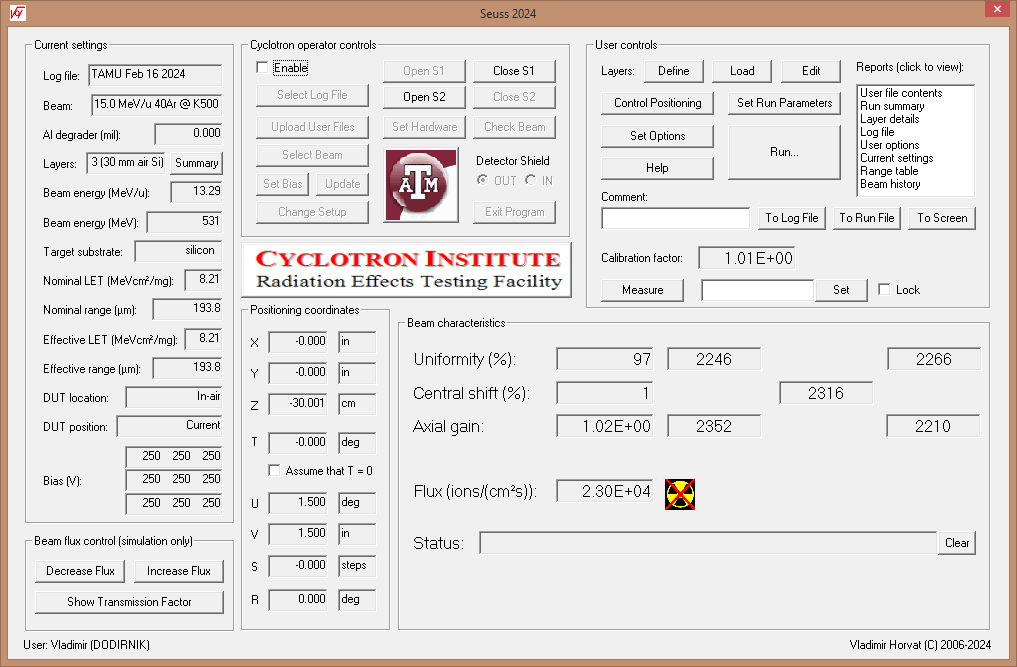
At the Cyclotron Institute Radiation Effects Facility, Texas A&M University, a program named Seuss is used to control the installed hardware components. If these hardware components are not detected, the program runs a simulation. This feature enables the users to become familiar with the software before arriving to the site. Seuss should run on any Windows operating system. However, because of the size of the application windows, the screen resolution should be at least 1024 pixels × 768 pixels. The screen snapshot below shows the main application window in its actual size.
The main application window is divided into several areas. Their purpose, usage, and functionality are described in the following sections.
Current settings group contains a set of read-only edit boxes that display the relevant information and static text that briefly describes their content. A more detailed information is provided below:
During the run, the beam flux is controlled exclusively by the Cyclotron Institute's personnel, based on user's requests. To learn about the effects associated with very low and very high beam flux, the Beam flux control group is provided for use when the beam flux is simulated. Functions of the buttons are described below:
Positioning coordinates group contains a set of read-only edit boxes that show the current position of the device under test (DUT) in terms of its coordinates X, Y, Z, and T. Coordinate T is the tilt angle of the mounting frame with respect to the beam. When the DUT is inside the vacuum chamber, X and Y are the horizontal and vertical coordinates of the DUT in the mounting frame plane, while the Z axis is horizontal and perpendicular to the mounting frame. When the DUT is in air, Z axis is along the ion beam axis, while X and Y are the horizontal and vertical coordinates, respectively, both being perpendicular to Z.
In the "Vacuum chamber" setup coordinates U and V specify the aperture of the horizontal and vertical slits, respectively. In the "In-air" setup coordinate U specifies the DUT roll angle, while coordinate V is unused.
Coordinates S and R specify the aluminum degrader thickness. S specifies the selected degrader and has to have an integer value. R is the tilt angle of the degrader. When S is zero, the beam is not degraded and R coordinate is irrelevant.. Otherwise, the effective degrader thickness in mil (1/1000 in.) equals 2S-1/cos(T). Values of R over 60° are not recommended because they result in large uncertainty of the degrader effective thickness. They can be avoided by increasing S (i.e., by using a thicker degrader).
The ion beam (average) flux, as well as its uniformity, central shift, and axial gain are continuously monitored using four scintillation detectors (scintillators) used as ion counters. They are located in the diagnostic chamber, at close distance upstream from the DUT, and are arranged so that they define a square centered around and perpendicular to the ion beam axis. The sides of this square are either horizontal or vertical. Therefore, each scintillator can be referred to according to its position as seen by the ion beam: top left (TL), top right (TR), bottom left (BL), or bottom right (BR). In the standard mode of operation (idle mode) an additional scintillator is placed centered on the ion beam axis. This scintillator is referred to as central ion counter (CIC). It is mounted on a shutter (the downstream shutter, S2) that blocks the ion beam and prevents the ions from reaching the DUT.
The signals from all five scintillators are repeatedly counted over one second intervals and the results are subsequently displayed in the appropriate edit boxes in the Beam characteristics group. After each interval, the current ion beam (average) flux, uniformity, central shift, and axial gain are calculated and displayed as well.
Calibration factor represents the axial gain averaged over a time interval long enough so that the collected number of counts from each ion detector reached or exceeded 10,000. The current value of this parameter is used during the run to estimate the ion flux, since the CIC is out of the way at that time.
Messages regarding the status of the program are displayed on the status bar. The Clear button next to the status bar can be used to erase the displayed message.
User controls group contains active controls that allow the users to set the values of the relevant parameters, position the DUT, limit the beam exposure of the DUT, and obtain various reports. The use of these controls generally results in the change of the mode of operation of the program or in the termination of the program followed by a launch of another program. The main application window is launched as the daughter window closes. Descriptions of the available controls can be obtained by clicking the links listed below.
Cyclotron operator controls group contains active controls intended primarily for the authorized Cyclotron Institute personnel. This group is initially disabled and can be enabled by checking the Disable checkbox. Users are generally discouraged from using these controls and are expected to notify the authorized Cyclotron Institute personnel if they intend to use them.
However, the users will need to use these controls in the simulation (demo) mode in order to specify the log file and the setup, select the appropriate beam, or exit the program.
Program Seuss produces ASCII files. Their content can be viewed, modified, or printed using NotepadTM or any other similar program. The log file does not have an extension. Files having the same name as the log file and extension #nn, where nn is any combination of two characters, are the run files. They contain the records produced when a run ends. A summary of all run data is contained in the report file that has the same name as the log file and extension rep.
Files that contain layer information have arbitrary names (specified by the users) and extension lay. Likewise, positioning information is contained in the files having extensions po1 and po2 for vacuum setup and in-air setup, respectively. A position file that was marked by the users as hidden will have extension po3 instead of po1 and po4 instead of po2.
Click here to learn about the newly implemented features not described above.
Any comments or suggestions regarding the control software or the information give above are welcome. Please direct them to the author at
(Vladimir Horvat)